From the simulation, a drilling template can now be produced in a printer-friendly manner.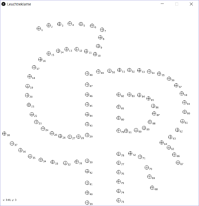
A PCB board has to be assembled.
This drill template can now be used to make the appropriate holes in an LED carrier (e.g. 3.2mm hardboard as used for furniture back panels).
The LEDs are inserted into the drilled plate and then soldered depending on the type used series resistors.
practice building
Create a drilling template and build up your neon signage practically. Solder the LEDs in desired manner, build a control PCB and connect to LEDs.
Generation of the drilling template
The drilling template can be generated from the simulation. It is used to drill suitable holes for the LEDs.
Connection of the LEDs
The LEDs must be connected in groups according to the ideas from the simulation. Suitable resistors must be selected.
The following circuits, for example, can be used for operation at a 5V DC voltage source.
| LED Colour | connection | Resistor value |
| Red and Yellow | Two LEDs connected in series with one resistor | 56 Ω |
| White and Blue | Single LED connected with resistor | 1,2 kΩ |
| Orange | Two LEDs connected in series with one resistor | 100 Ω |
| Green | Two LEDs connected in series with one resistor | 15 Ω |
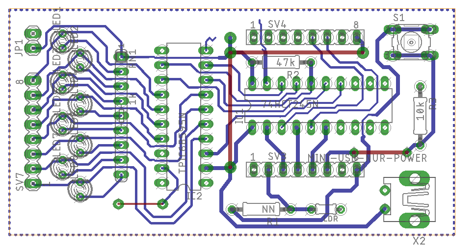
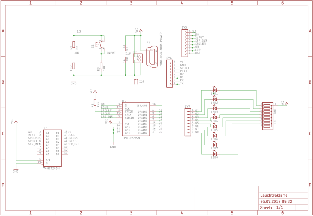
PCB Board
In order to enable a connection with the microcontroller WEMOS D1 mini, a circuit board was developed which enables the control of 8 LED groups with 150mA each.
The board enables the control of up to 8 LED groups with higher currents. A driver module and a level converter are built in, since the WEMOS only works with a voltage of 3.3V, in contrast to the rest of the circuit, which is operated with 5V.
In order to be able to manufacture them easily, a one-sided version was designed in addition to the two-layer circuit board.
Download the complete Eagle PCB Layout:
In this version the connection of the PIR sensor for the detection of the presence of persons is still missing. This feature has to be added.